Project 2.1.1 Majority Vote
The purpose of this project was to use simplified and unsimplified logic expressions, AOI circuits, Boolean Algebra and bread boarding to create a voting machine that simulates four members voting on a decision. The process started as a truth table, then to an unsimplified logic expression and AOI circuit. After the use of Boolean Algebra, we created a simplified expression and AOI circuit and then created the breadboard below.

A truth table is used when working with logic expressions and Boolean algebra to show when an expression is true or not true. The 1 means that the minterm is on or is true, and a 0 means that the minterm is off or not true.
For this truth table, we used four different members, P (the President), V (the Vice President), S (the Secretary), and T (the Treasurer). Each of the members could either vote a 'Yes' (1) or 'No' (0). With four members, there was sixteen possible outcomes for the decision. If the decision were to be a 1, a majority of the members needed to vote 'Yes' (1). If the vote is at a tie, the decision is broken by the President. If the President votes 'Yes' (1) the decision will pass, but if the President votes 'No' (0) the decision fails.
From the truth table, you can write an un-simplified logic expression, and from there, a simplified one. The un-simplified expression is in a Sum-Of-Products form (SOP). The expression is in SOP form because the minterms went through the AND gates, and then through the OR gates in the expression. The SOP form is also easier to read in this case because one event could happen (product) OR (sum) another event could happen.
The un-simplified expression was:
D= notPVST+PnotVnotST+PnotVSnotT+PnotVST+PVnotSnotT+PVnotST+PVSnotT+PVST.
According to the expression, the following groups of people could vote and the decision would pass:
- The Vice President, Secretary, and Treasurer
- The President and the Vice President
- The President and the Secretary
- The President, Secretary, and Treasurer
- The President and the Treasurer
- The President, Vice President, and the Treasurer
- The President, Vice President, and the Secretary
- The President, Vice President, Secretary, and the Treasurer
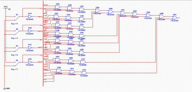
This is the un-simplified circuit, created using the MultiSim program. The program allows for you to create circuits and test them within the program before you make the actual bread board.
This circuit is known as an AOI circuit, because it uses AND, OR and INVERTER gates. There is a VCC used to generate the power, and a ground, so that the different components can be grounded within the circuit. The bus, the thick red line in the center, allows for easier organization of the wires. In this circuit, there is four inverter gates, twenty four AND gates, and seven OR gates. With that many gates, there would need to be eight 74LS08 chip, one 74LS04 chip, and two 74LS32 chips.
This circuit is known as an AOI circuit, because it uses AND, OR and INVERTER gates. There is a VCC used to generate the power, and a ground, so that the different components can be grounded within the circuit. The bus, the thick red line in the center, allows for easier organization of the wires. In this circuit, there is four inverter gates, twenty four AND gates, and seven OR gates. With that many gates, there would need to be eight 74LS08 chip, one 74LS04 chip, and two 74LS32 chips.

Boolean Algebra is theories and equations that can be used to help simplify long un-simplified expressions. Some theories can included Communitive Law, Associative Law, Distributive Law, Consensus Theorems, and DeMorgan's Theorems.
The simplified expression, after all of the Boolean Algebra used:
D=PS+PT+PV+VST
The simplified expression, after all of the Boolean Algebra used:
D=PS+PT+PV+VST
The simplified circuit used far less chips and gates, but still included a bus to organize the wires. Even though I didn't need any inverters, there are still some in the circuit.
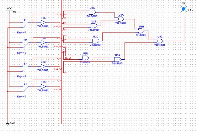
The simplified circuit was created in the MultiSim program. Like the un-simplified circuit, this circuit has a VCC power, a ground, a bus, inverter gates, AND gates and OR gates. The only difference is that a LED light is attached to the circuit so that the expression can be tested. There were only five AND gates that were used and only three OR gates needed for this circuit. Because each chip has four gates in it, I needed two 74LS08 chips and one 74LS32 chips.
The simplified circuit contained fewer gates, which meant that it required fewer chips. The un-simplified circuit had four inverter gates, but the simplified circuit doesn't require any. There were twenty four AND gates in the original circuit and with the simplified circuit, I only need five gates, cutting my need for eight 74LS08 chips to a need of only two and only one 74LS32 chip from my previous need of two chips. It would be cheaper to create the simplified circuit, because I would need less chips overall. If I created the un-simplified version, it would be too expensive to create on a mass scale.
The simplified circuit contained fewer gates, which meant that it required fewer chips. The un-simplified circuit had four inverter gates, but the simplified circuit doesn't require any. There were twenty four AND gates in the original circuit and with the simplified circuit, I only need five gates, cutting my need for eight 74LS08 chips to a need of only two and only one 74LS32 chip from my previous need of two chips. It would be cheaper to create the simplified circuit, because I would need less chips overall. If I created the un-simplified version, it would be too expensive to create on a mass scale.

Majority Vote Circuit Bill Of Materials
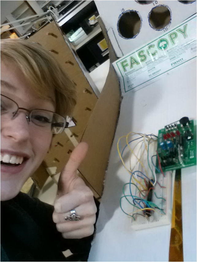
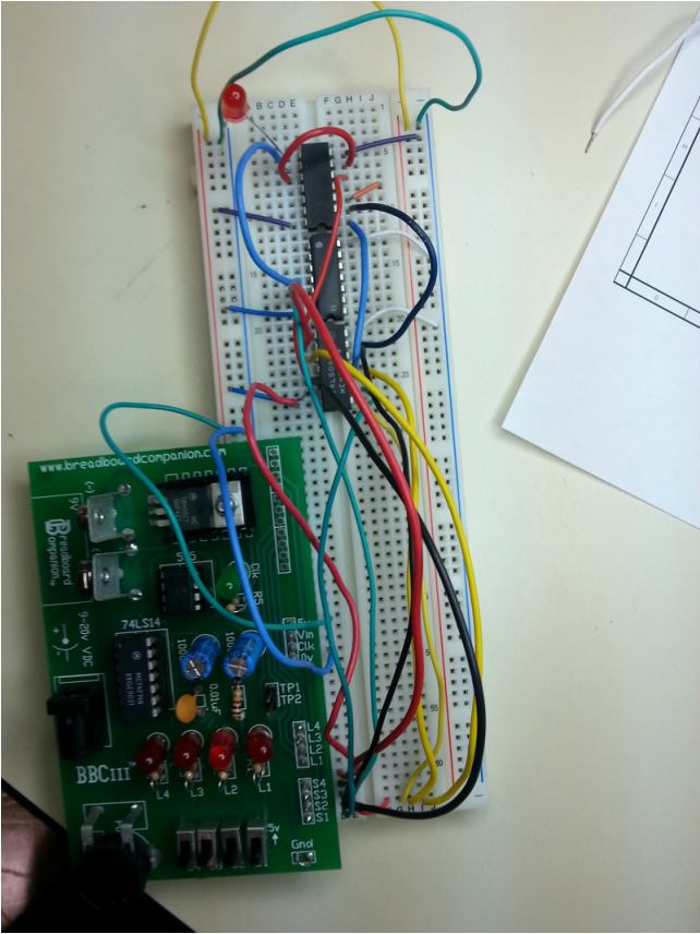
Bread boarding was not easy for me the first time that I did. This project wasn't the first time we bread boarded, and I had many difficulties before this. It was difficult for me to understand the gates within the integrated circuits, but with practice I began to understand them better. With this project, it was difficult in organizing which wires belonged where, and colour coding the wire and the minterm helped with the confusion. Luckily, when I tested my breadboard the first time, I had everything in order and the logic expression worked, and the LED turned on when it was supposed to, and stayed off when it should of had.
Overall, I enjoyed this project. This project showed the ability to simplify logic expressions, use Boolean algebra, infer truth tables, and work with integrated circuits. Boolean algebra is helpful because it takes very long expressions and helps shorten them. We created the un-simplified expression in multi-sim, simplified it, remade it in mult-sim and then created the circuit in real life using the bread boards and breadboard companion.
BREAD AND CHEESE ISN'T A TERRIBLY HEALTHY DIET
